Picking a cable looks simple: find the current, look up the size, buy the wire. That works for a short run in a cool room. It fails in a riser in Singapore, and it fails hot — the cable ends up too small, not too large.
There are six checks, not one. Three of them are the reason the table answer moves.
The six checks, in order
The order of these checks is critical. The corrections multiply, and the small-conductor cap is applied after them, not before — the reverse of how most people approach it.
- Work out the design current.
If the load runs for three hours or more without a break — an EV charger, a water heater, most air conditioning — multiply the load current by 1.25. Otherwise the design current is the load current. This is the number every later step is measured against.
- Read the base ampacity.
Find the smallest conductor whose table ampacity is at least the design current. Every published ampacity table assumes an ambient of 30 °C and no more than three current-carrying conductors bundled together. If your installation matches those assumptions, the next two corrections do not apply.
- Correct for ambient temperature.
Multiply the table ampacity by the correction factor for the temperature the cable actually sits in. For a 75 °C conductor the factors run 0.94 at 31–35 °C, 0.88 at 36–40 °C, 0.82 at 41–45 °C and 0.75 at 46–50 °C. A riser, a ceiling void above a flat roof, or a plant room in the tropics will sit in the middle of that range for most of the year.
- Correct for grouping.
If more than three current-carrying conductors share a conduit or tray, they warm each other and the ampacity falls again. This factor multiplies with the ambient one; it does not replace it.
- Apply the small-conductor cap.
For the three smallest common sizes there is a hard ceiling on the overcurrent device, regardless of what the ampacity table says: 15 A for 14 AWG, 20 A for 12 AWG, 30 A for 10 AWG in copper. This step is what most calculators miss. The cap applies after the other corrections; the code is explicit that the ambient and conductor-count factors come first.
- Check voltage drop, then take the largest answer.
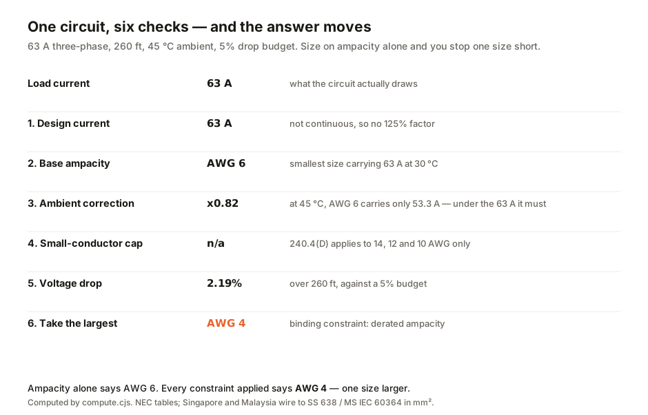
Voltage drop is a separate constraint from heat, and on a long run it usually governs. Size for it independently, then take whichever of the answers is largest. Ampacity is about heat: can the cable carry the current without cooking? Voltage drop is about delivery: will the load see enough voltage at the far end? A cable can easily pass one test and fail the other.
Four circuits, worked
These are computed, not illustrative. The last column is the constraint that actually decided the answer.
| Circuit | Design current | Ambient factor | Answer | Decided by |
|---|---|---|---|---|
| 20 A sockets, 30 ft, 30 °C | 20 A | 1.00 | 12 AWG | small-conductor cap |
| the same circuit, 40 °C riser | 20 A | 0.88 | 12 AWG | derated ampacity + cap |
| 32 A EV charger, continuous, 130 ft, 40 °C | 40 A | 0.88 | 8 AWG | all three |
| 63 A submain, three-phase, 260 ft, 45 °C | 63 A | 0.82 | 4 AWG | derated ampacity |
The first two rows are the useful pair. Nothing about the load changed between them — same 20 A, same 30 ft, same budget — and the answer did not change either. What changed is why: in the cool room the small-conductor cap alone forces 12 AWG, and in the riser the derated ampacity would have forced it anyway. The result is the same, but the reasoning is different. That is common, and it is why skipping a step seems fine until the one time it is not.
When these steps do not change anything
The 32 A EV charger is the honest case. All three constraints bind on it, and the answer is 8 AWG — which is exactly what you get from base ampacity alone. Doing the full procedure on that circuit changes nothing at all.
To be clear, these corrections do not always change the answer. A guide that only showed the edge cases would be misleading. On a short run, in a cool space, with a load well clear of a cap boundary, the table answer is the right answer. The corrections matter when you are close to a boundary — and you cannot know whether you are close without doing them.
What this audit found in our own tools
Every guide here reads the source of the tools it links, and this one found two defects. Both have been fixed; both are described because the reasoning is more useful than the patch.
Our wire-size calculator applied no corrections and no cap. It picked the smallest conductor whose raw table ampacity met the design current, then checked voltage drop. Swept across seven loads, five returned a conductor whose overcurrent cap is below the load — a 20 A circuit was answered 14 AWG, which is capped at 15 A. The tool's own explanatory copy already listed the correct caps, so its text and its arithmetic disagreed, and the text was right.
Our voltage-drop calculator recommended the same size for everything. Its recommendation loop walked the conductor table with Object.entries, and JavaScript orders integer-like keys numerically ahead of the rest — so the walk began at 1 AWG, a service-entrance conductor, which satisfies almost any drop budget and ended the loop immediately. Every input tested returned "AWG 1 or larger". The bug erred toward over-sizing, so it was a correctness problem, not a safety one. Still, it was recommending service-entrance cable for lamp circuits.
Both now run through a shared kernel with the correction tables, the caps and the termination-rating clamp in one place, under test. The figures in this guide come from an independent implementation. It agrees with the new kernel on 4 of 4 worked circuits, which is the only reason we are willing to tell you what our calculator will say.
Measure the ambient where the cable runs, not where the board is. A riser is hotter than the room it leaves, and the correction factor accounts for that difference. Apply the small-conductor cap last, after the temperature and grouping corrections, because that is the order the rule is written in. Size for heat and for voltage drop separately and take the larger — they are different failure modes and a cable can pass one while failing the other. Treat any answer within one size of a cap boundary as needing the full procedure, since that is exactly where skipping a step changes the outcome. And have the design checked by a licensed electrician, which is not a disclaimer so much as the last step of the method.
Run your own numbers
Our wire size calculator now runs all six checks and shows the derated ampacity and the binding constraint alongside the answer, so you can see which step decided it. The voltage drop calculator handles step six on its own if you already know the size and want to test the run length. For the loads themselves, the Ohm's law calculator converts between watts, volts and amps, and the resistor colour code calculator is the one to reach for when you are reading components rather than sizing feeders.
- Every figure in this guide is computed by a script committed alongside it, which sizes each circuit twice: once with an implementation written from the standards, and once with the shared kernel our own calculators use. The guide may only state a number both produce, and the script exits non-zero if they diverge. The two agree on all four worked circuits.
- Small-conductor overcurrent caps are NEC 240.4(D): 15 A for 14 AWG, 20 A for 12 AWG, 30 A for 10 AWG in copper, applied after the ambient and conductor-count corrections. Ambient correction factors are NEC Table 310.15(B)(1) for 75 °C conductors on a 30 °C base. Both read 2026-08-08 and cited in full in the computation script.
- The ampacity table used is the 75 °C copper column of NEC Table 310.16 — the table our own calculator ships, quoted from its source file so the comparison between the old answers and the new ones is like for like.
- ⚠️ NEC is a United States code, and the sizes above are AWG. Singapore and Malaysia wire to SS 638 and MS IEC 60364 in metric mm², with their own tables and their own correction factors. The procedure — design current, ampacity, ambient, grouping, cap, voltage drop, take the largest — is the same in both, and it is the procedure this guide is about. Do not carry these AWG numbers into a metric design.
This is an explanation of how conductor sizing is calculated, not a design, and it is not a substitute for the wiring regulations in force where you are. Electrical work is licensed in most jurisdictions for good reason. Have any circuit you intend to build checked and signed off by a licensed electrician.

View author profile → · Editorial policy